The Lightning Protection Institute is a nationwide not-for-profit organization founded in 1955 to promote lightning protection education, awareness, and safety. The lightning protection industry began in the United States when Benjamin Franklin postulated that lightning was electricity, and a metal rod could be used to carry the lightning away from a building. Lightning is the direct cause of over 50 deaths and 400 injuries each year, and it is difficult to protect individuals in exposed outdoor areas. Direct lightning strikes cause fire damage in excess of $200 million per year, and insurance companies pay claims in the billions of dollars associated with lightning either directly or indirectly. Most of these property losses could be minimized, if not eliminated, through the implementation of proper lightning protection for structures. LPI is dedicated to ensuring that today’s lightning protection systems provide the best possible quality in both materials and installation practices for maximum safety.
The National Fire Protection Assoc. (NFPA) publishes document # 780 titled Standard for the Installation of Lightning Protection Systems considered the national design guide for complete lightning protection systems in the United States. NFPA published its first document on lightning protection in 1904. NFPA documents like the National Electrical Code (NEC – NFPA 70), National Fuel Gas Code (NFPA 54), and Uniform Fire Code (NFPA 1) are developed by the committee process to review acceptance of new safety information on specific fire related subjects.
The lightning protection Standard # 780 is reviewed on a three-year cycle for updating. NFPA 780 includes lightning protection for typical building construction in Chapter Four as requirements for ordinary structures. The 780 document covers many specialty constructions from hazardous materials storage to boats and ships to open picnic structures, and gives recommendations for personal safety outdoors. NFPA 780 provides the best we know today in theory and technology on protection systems tested by experienced industry professionals in a legally recognized format.
Product testing for lightning protection material components in the factory prior to shipment for listing and labeling is handled by Underwriters Laboratories, Inc. (UL). The UL Standard 96 addresses the minimum requirements for construction of air terminals, cable conductors, fittings, connectors, and fasteners used in quality lightning protection systems. UL has inspection personnel who visit production facilities on a regular basis to verify compliance for continued use of their approved merchandise labels.
![]()
Field inspection of completed lightning protection installations may also be arranged with UL through installing contractors listed in their program. UL has issued a “Master Label” product for systems fully compliant with their Standard UL 96A for many years. Standard 96A is based on the general requirements of NFPA 780, but UL has a Standards Technical Panel (STP) to review the requirements for a more inspectable format which leads to some differences. UL will also inspect to some other nationally recognized Standards (like NFPA 780) for fully compliant systems. Some partial constructions may be available for field inspection under their “Letter of Findings” program.
The Lightning Protection Institute (LPI) adopts the latest edition of the NFPA 780 Standard as its reference document for system design. LPI advocates use of UL as the third-party inspection authority for components according to their documents UL 96. LPI publishes this document # 175, based on NFPA 780, with additional explanatory material helpful to installer and inspector member personnel.
LPI provides the industry self-policing testing program for Journeyman, Master Installer, and Designer Inspector Certification of members. Individuals sit for exams which include the requirements of the above listed lightning protection Standards and application of those principles to design examples. Membership renewal is required each year with additional examinations taken approximately every three years when the national Standards are updated. Contracting with professionals qualified through the LPI process ensures an added level of quality assurance for initial system installation and a resource for future inspection and maintenance of existing systems.
LPI has implemented an inspection program for completed installations under the name LPI-IP. LPI-IP provides a certification service more thorough and complete than any previous inspection program from LPI or others currently available in the marketplace. Through the use of check points, reviews, and on-site inspections, LPI-IP system certification ensures safety using qualified installer personnel and independent inspectors. LPI-IP offers a “Master Installation Certificate” for complete structures, a “Reconditioned Master Installation Certificate” for previously certified constructions, and a “Limited Scope Inspection” for partial systems in designated contracts. This is a critical element to the specifier, owner, and property insurer providing verification by a third-party independent source of quality lightning protection installations.
Lightning protection systems for structures are typically not a requirement of national building codes, although the Standards may be adopted by the authority having jurisdiction for general construction or specific occupancies. Since lightning protection may be considered an option, it is crucial that the specifier, construction contractor, and property insurer be familiar with the national Standards to provide the highest level of safety available. Lightning protection systems have a remarkable record of protecting against physical danger to people, structural damage to buildings, and failure of internal systems and equipment. The value received begins with proper design, continues through quality installation practices, and must include inspection and certification. The ultimate goal is safe haven, security of investment, and elimination of potential system downtime in opposition to one of nature’s most destructive events.
General System Information
The Standards in the United States for complete lightning protection systems include NFPA 780, UL 96 & 96A, and LPI 175. These Standards are based on the fundamental principle of providing a reasonably direct, low-resistance, low impedance metallic path for lightning current to follow, and making provisions to prevent destruction, fire, damage, death, or injury as the current flows from the roof levels to below grade. The Standards represent a consensus of authorities regarding basic requirements for construction and performance of qualified designs and products. Based on sound engineering principles, research, records of tests and field experience, a complete protection system is expected to create personal and structural safety from lightning and its secondary effects. The Standards are under continuous review for new products, construction techniques, and validated scientific developments to address the lightning hazard. Although material components may appear very similar, the configuration of a total system design has changed dramatically over the last 25 years to reflect today’s lifestyles.
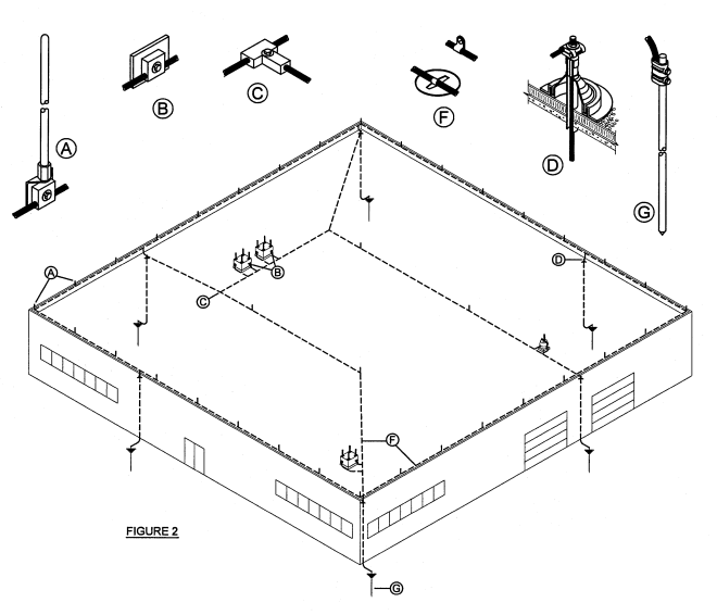
There are five elements that need to be in place to provide an effective lightning protection system. Strike termination devices must be suitable to accept direct lightning attachment and patterned to accept strikes before they reach insulated building materials. Cable conductors route lightning current over and through the construction, without damage, between strike terminations at the top and the grounding electrode system at the bottom. The below grade grounding electrode system must efficiently move the lightning to its final destination away from the structure and its contents. Bonding or the interconnection of the lightning protection system to other internal grounded metallic systems must be accommodated to eliminate the opportunity for lightning to sideflash internally. Finally surge protection devices must be installed at every service entrance to stop the intrusion of lightning from utility lines, and further equalize potential between grounded systems during lightning events. When these elements are identified properly in the design stage, incorporated into a neat workmanlike installation, and no changes to the building occur, the system will protect against lightning damage. Elements of this passive grounding system always serve a similar function, but the total design is specific for each particular structure.
Lightning protection components are made from materials that are resistant to corrosion and they must be protected from accelerated deterioration. Many system components will be exposed to the atmosphere and climate. Combinations of materials that form electrolytic couples in the presence of moisture shall not be used. Current carrying system components must be highly conductive. Prevailing site soil conditions will impact in-ground system components. The system life and maintenance/replacement cycle is dependent on material choice and the local environment. System materials must be coordinated with the structural materials in use – including flashings, copings, ventilator housings, various roofing systems – to maintain the moisture envelope for the intended life of the building.
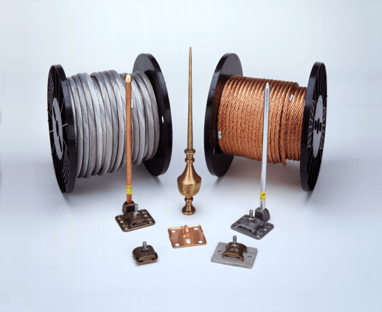
Copper, copper alloys (including brass and bronze), and aluminum are the basic system component materials. They serve the best combination of function for current carrying and weathering. Since aluminum materials have slightly lower current carrying capability and mechanical strength than similar sized copper products, listed and labeled materials for lightning protection include larger physical size parts. For example to be considered equivalent, a minimum size air terminal would be ½” diameter in aluminum, versus 3/8” diameter in copper.
Water running off copper will oxidize aluminum and galvanized surfaces, so coordination of system design must include galvanic considerations for potential mounting problems. Qualified bimetallic fittings are used to coordinate system components for required transitions from aluminum to copper. These may include listed products for the purpose, or in some cases stainless steel components. Aluminum can never come in contact with the earth or soil. Aluminum should never contact alkaline based paint surfaces or be embedded directly in concrete.
If any product is subject to unusual mechanical damage or displacement, it may be protected with a molding or covering, but care must be exercised to allow strike terminations and other roof mounted components to serve their function in accepting attachments. Lightning protection components below the strike terminals may be concealed within the building below the roof level during construction or when accessible. The speed of lightning current and splitting the flow among multiple paths will not permit components to heat to any instantaneous ignition temperature hazardous to typical building materials. Incorporating the system into the construction allows interconnection of structural metal framing and internal grounded systems, and provides protection against displacement and maintenance issues which are beneficial in extending the life of a system.
Materials suitable for use in lightning protection systems are listed, labeled, and tested according to UL Standard 96. Consideration for conductor design includes maximizing surface area to carry lightning and flexibility of the configuration to make bends and turns required in installation practices. Air terminal bases efficiently accomplish the transfer of a strike from termination device to cable conductor and securely mount to various building surfaces under severe weather conditions. Splicing fittings must maintain contact with conductor lengths adequate to accomplish current transfer and weather the exposed environment. Grounding electrodes must provide the proper earth contact to disperse the charge and satisfy requirements for life cycle suitability in various soil compositions. Bonding devices are sized to provide adequate interconnection of systems to create potential equalization throughout the structure. Surge Protection Devices are qualified at higher current levels to meet the needs associated with lightning attachments.
Strike Termination
Strike termination devices serve the system function of accepting the direct lightning attachments. They represent the umbrella against penetration of lightning to non-conductive building materials to guard against fire or explosion. Any metallic body 3/16” thick or more projecting above a structure will accept a lightning strike without burning through. Therefore, in some cases construction elements may be incorporated as strike terminations. Tall masts or overhead ground wires similar to power transmission line protection may serve as strike terminations. In most cases, however, small specific purpose air terminals constitute the majority of strike termination systems. These unobtrusive components are preferred for ease of mounting and aesthetic reasons, and can be coordinated into a most effective configuration for all typical building constructions.
The atmosphere surrounding us is electrically charged, but free air maintains a relatively balanced ion distribution. When we raise a building into the air, a tree or even a person to a lesser extent, we change that electrical balance. The electrical field accumulates to change points in the geometry of ground mounted objects. Items like ridges and particularly ridge ends, edges of flat roofed buildings and even more the corners become points of accumulation for ions that increase susceptibility to lightning attachments. A proper system of strike termination devices accounts for these realities by using air terminals in a configured pattern designed to use the building’s points of natural ionic accumulation to pull lightning into the protection system. The taller the structure and the more severe the planar changes (like a vertical wall to a horizontal flat roof) the greater the opportunity for attachment at these critical junctions. Designing a system of air terminals projecting only 10 inches above these structural points of emphasis and along ridges and edges has been proven, in more than a century of practice, to provide interception of some 95% of recorded lightning flashes, including the most violent. Some lower potential lightning strokes could theoretically attach on flat planes away from strike terminations designed to the Standards, but the consequences are within acceptable limits for ordinary construction. Considering the lower energy level required for a bypass, the other structural grounding components included in a complete lightning protection system, and the random probability for connection with a system component anyway, this method of building protection is considered most efficient.
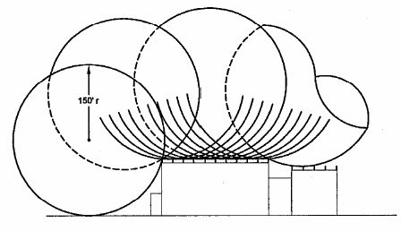
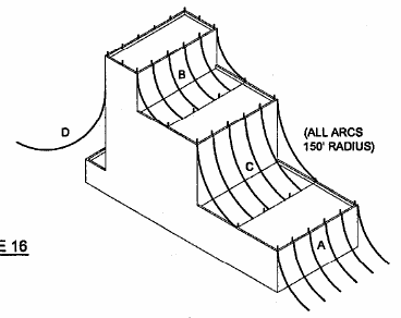
Protecting the highest most prominent building elements with strike termination devices, based on a building’s geometry, also provides some level of protection for lower extensions of the structure, or items in the “shadow” of the higher fully protected areas. A zone of protection exists from any vertical strike termination device and more than that from a vertical fully protected building level. Zone of protection is described in the lightning Standards using a 150 feet (46 meters) radius sphere model to identify items under the protection of higher system elements or building extensions to distances that require further protection by additional strike terminals. This is like rolling a 300 feet (92 meters) diameter ball from grade up against and then over a building to the opposite grade level in every conceivable direction. If the ball touches insulated building material, then an additional strike terminal is added. Areas supported by strike terminals, a strike terminal and grade, and vertical walls are then under the protection of properly designed system elements. This geometric model for protecting total structures is based on the last step in the lightning attachment process, and again covers well over 90% of conceivable strikes. On more critical structures, like those containing explosives or flammable liquids and vapors, the model is reduced to a 100 feet (30 meters) radius sphere that covers in excess of 98% of recorded lightning strikes.
The strike termination system defends the structure against lightning attachment by providing preferred attachment points. Copper or aluminum air terminals are preferred in most cases based on their conductivity and suitability to exposure to weather. Qualified prominent metallic building elements may also serve the function. In special circumstances where lightning cannot be allowed to penetrate, the use of tall masts and overhead ground wires used in a reduced zone model can provide additional protection. Protecting things like lighting standards or trees can provide some area protection based on the zone model. Strike termination design configuration is the first key element to providing a complete lightning protection system.
Conductors
The conductor system component of complete lightning protection includes main sized cables, the structural steel of a building, and bonding or interconnection wires to internal grounded building systems. The main conductors perform the current carrying function from the strike termination devices to the grounding system. Main cables are highly conductive copper or aluminum that perform well in an external environment. Lightning seeks a path toward ground, so even with very conductive materials, the routing of cables needs to be maintained in a horizontal or downward coursing. This is similar in concept to the gravity flow of water on sloped flat areas to roof drains or in gutter to downspout systems. Cables need to be routed using long smooth bends of no less than 90 degrees. Lightning will place significant mechanical force on cables, and sharp bends or corners can be damaged or lightning can arc over in the worst cases. This mechanical force can be compared to sending pressurized water through a fire hose – the conductor will try to straighten itself creating a damage concern for splice fittings, fasteners, or the conductor itself.
Copper and aluminum main cable conductors for lightning protection are designed to a smooth weave or rope-lay standard using smaller gauge individual wires. This construction allows a maximum surface area per unit weight of conductor to accommodate lightning which travels quickly on the surface. This construction also allows for easier bending and forming of the conductor system along, around and over building construction elements. Exposed conductors are fastened at maximum three feet intervals to maintain the system in place against wind and weather. All strike termination devices must be connected to the conductors with a minimum of two paths to the grounding system. Strike termination devices covering various areas of a structure must be interconnected to form a single system either by roof conductors, at down conductors, or by interconnection of grounding system elements for different roof levels or projections. Lightning cable conductors may be concealed below or within construction – in attics and wall spaces, or in concrete pours – because the speed of lightning lowers the potential for heating of the conductors to the spark ignition temperature of building materials to well below damaging levels.
Downleads or down conductors are the elements of the main conductor system that generally bring the lightning from the roof level system to the grounding system. This may include cable conductor, or qualified continuous steel framework of 3/16” thickness or greater, or a combination. Reinforcing steel or rebar is not acceptable as a substitute for cable conductor, but each cable downlead must be bonded to the structural framing at the top and bottom of each vertical run. All strike termination devices must have a minimum of two paths to ground to split the lightning along multiple paths, so the smallest building must have two downleads minimum. Downleads for large buildings may be calculated at 100 feet average intervals for the perimeter footprint of the building, although system components for special building design elements may necessitate additional down conductors to meet multiple path requirements. It is important to calculate the footprint of the protected perimeter to get the proper distribution for downleads for ridged roofs which include strike terminations only along the apex.
Providing multiple paths for lightning current has the great advantage of lowering the total energy on any given conductor. This impacts not only conductor sizing, but also keeps the lightning to our specified paths to minimize side-flashing to internal systems and lessen potential internal induction problems. The lightning protection Standards call for a minimum number on the perimeter, but more paths can be very beneficial in providing a cage of protection for equipment and people inside. The fact that steel frame construction creates the largest number of qualified vertical paths interconnected horizontally on multilevel structures makes its use as downleads preferred to give an improved shield against lightning side-effect intrusion. Although cable conductors are required for downleads in poured concrete construction, the required bonding of the rebar helps create a similar network of protection in high rise construction projects.
Grounding
Properly made ground connections are essential to the effective functioning of a lightning protection system, as they serve to distribute lightning into earth ground. This does not mean that the resistance of the ground connection must be low, but rather that the distribution of metal in the earth, or upon its surface in extreme cases, shall be such as to permit the dissipation of a lightning discharge without causing damage.
Low resistance is desirable but not essential, as may be shown by the extreme cases on the one hand of a building resting in moist clay soil and on the other hand by a building sitting on bare rock. In the first case, if soil is of normal resistivity, the resistance of a proper grounding electrode would be expected to be less than 50 ohms, and two such connections to ground on a small rectangular building have been found by experience to be sufficient. Under these favorable conditions, providing adequate means to dissipate the energy of a flash without chance of serious damage is a simple matter. In the second case, it would be impossible to make a good ground connection in the ordinary sense of the term, because most kinds of rock are insulating or at least of high resistivity; hence, in order to obtain an effective ground, more elaborate means are necessary. The most effective systems consist of an extensive wire network laid on the surface of the rock surrounding the building to which the down conductors are connected. The resistance between such an arrangement and earth may be high, but at the same time, the potential distribution about the building is substantially the same as though it were resting on conducting soil and the resulting protective effect is also substantially the same. The lightning protection grounding electrode system serves to take the lightning into whatever soil strata exists, and route it away from the structure.
A grounding electrode network will be determined largely by the experience and judgment of the person planning the installation with due regard to the minimum requirements of the Standards, which are intended to cover the ordinary cases that are likely to be encountered, keeping in mind that, in general, the more extensive the underground metal available, the more effective the grounding system. The grounding arrangement depends on the character of the soil, ranging from single ground rods where soil is deep, to the use of multiple electrodes, ground plates, radials, or buried wire networks where soil is shallow, dry, or of poor conductivity. Each downlead cable shall terminate to a grounding electrode connection dedicated to the lightning protection system. Electrical or communication system electrodes must not be used in lieu of lightning ground electrodes. The final product must include the bonding together of separate grounding electrodes of different systems.
Wherever practical, connections to grounding electrodes should be made exterior to the foundation wall or far enough away to avoid buried footings, pipe caps, etc. Grounding electrodes should be installed below the frost line where possible. The materials used for grounding electrodes must be suitable to any alkaline or acid composition of soils for long life.

During a discharge of lightning current on a system of conductors, the grounding electrodes are to be thought of as the points through which the heavy current flows between the strike termination system and the earth about the structure. Therefore, placement with the view of carrying the flow of current away from the structure in the most advantageous manner is important. This will be realized by placing grounding devices at the outer extremities, such as corners and outside walls of the structure, and avoiding as far as possible the flow of current under a building. In some cases, particularly when additions to an existing building are involved, it may be necessary to place downleads and grounding inside and under a structure.
A ground loop encircling a structure interconnecting all downlead cables at their base and/or grounding electrode devices is the best way to equalize potential for an entire lightning protection system. It is always possible to have varying resistance values for grounding electrodes even on the same structure.
Since splitting the lightning along multiple paths begins at the strike termination point and follows through the conductor system to ground, different resistance values of electrodes can upset this function. An in-ground loop solves this potential problem and provides an extensive wire network to enhance the grounding system. A ground loop is required for every structure exceeding 60 feet in height. If an interconnecting loop cannot be installed in the earth, then it may be placed within the construction to fulfill this requirement. This ground level loop also accommodates connection with other building grounded systems.
All grounding media in or on a structure shall be interconnected to provide a common ground potential using main size lightning conductor. This includes the lightning protection grounding electrode system, electric, communication, and antenna system grounds along with metallic piping systems entering the structure like water, gas and LPG lines, metal conduits, etc. Interconnection to gas lines shall be made on the customer side of the meter to avoid defeating any cathodic protection of service lines. Where all these systems are bonded to a continuous metallic water line system, only one connection is required between the lightning protection grounding and the water line. System interconnection may be made at multiple points near structure entrances for systems, or one hard connection at a ground bar may be used. Bringing all building grounded systems to the same potential at grade is the first step toward protecting internal components and people from lightning. It begins the bonding process against side flashes from system components to internal building systems.
Potential Equalization (Bonding)
The major current carrying components of the lightning protection system were described in their earliest form by Benjamin Franklin. Modern techniques for component manufacture and designs incorporating the system on and in a structure have changed the system look, but the philosophy behind strike termination, conduction, and grounding remains similar – accept the lightning and send it to ground. The most dramatic changes involved in lightning protection system design come from adaptations in how we build and outfit the modern building, or what we might call the “indoor plumbing factor”. The modern building counts metallic piping like plumbing, sewer, and gas systems, along with circuitry for electrical and communication systems, which all provide internal paths for lightning to damage components and bring people closer to danger.
At the inception of a lightning strike to a system, there may be an immediate rise to 1,000,000 volts at prominent components traveling to 0 volts at earth ground. Any other independently grounded building system in close proximity to lightning protection components would be at 0 volts, so the natural tendency is for some or all the lightning to leave our current carrying system and flash over to the alternate ground path. If the distance between potential paths is short enough the arc over or sideflash may occur through air or building materials, either of which creates the potential for fire or explosion.
Since internal grounded building systems permeate a structure, this potential exists at roof level, on or in building walls, and even potentially below grade. Lightning spreads out from system grounding electrodes near the earth’s surface and can return on metallic pipes or other grounds back into the building. Alternate paths from interior grounded circuitry are not designed to carry lightning current (a fire hazard), and junctions in metallic pipes are not designed as current carrying devices leading to heat deformation or shock problems. Equipment within structures, from a sink connected to both the water and sewer lines to a personal computer connected to both the electric power and phone or antenna circuits, become additional points for lightning current to arc between independently grounded systems creating significant havoc.
A complete lightning protection system addresses this issue through bonding or the interconnection of metallic building systems with the lightning system to create a common ground potential. When grounded systems are bonded together there is no reason for the lightning to leave our designed current carrying path because the arbitrary arc over points don’t exist. It is required to interconnect every grounded building system and continuous metallic piping system with the lightning protection grounding electrode system near grade level. Low profile structures may only need interconnection of systems near the roof level when they are in close proximity to lightning protection system components. As structures get taller, it becomes a requirement to interconnect the top of the vertical extension of each internal grounded system with the lightning protection roof system. Finally, in high rise construction, building grounded systems are interconnected at grade level, roof level, and at intermediate levels to provide sufficient potential equalization between long conductor runs to avoid arc over.
Internal arcing between grounded systems is also a function of how many paths we have from the roof lightning protection system to the grounding system. The more paths the more we split the lightning into lower voltage segments, the less potential for arc over through any medium to alternate systems. Incorporating a steel superstructure into the lightning protection system provides columns and beams and intermediate connections to maximize splitting the lightning and thus minimize difference of potential problems internally. Standards require the interconnection of cable downleads to reinforcing steel (rebar) in poured columns at the top and bottom of each run creating a similar effect, although this mechanical structural system is not deemed suitable for carrying lightning current by itself. The reinforcing steel, grounded internal systems and lightning protection must also be interconnected at 200 feet vertical intervals to maintain potential equalization.
Bonding together of grounded systems is typically accomplished with smaller fittings and cables or wire runs on roof areas of structures. Interconnection for potential equalization is simply not the same as providing current carrying capability. However in many cases it is easier to use full size system components because designs place them close to desired bonding points. When we bond within construction or below grade it is more typical to use full size components mainly for a more robust mechanical strength against construction realities.
Extension of the lightning protection system to include grounded system bonding for any structure is a critical element based on the individual design of the building for the occupancy and processes specific to its intended use.
Surge Protection
Lightning protection systems are designed first and foremost as fire protection systems – to stop the building from burning down and losing the people and equipment inside. Bringing metallic services into a structure provides paths for lightning to follow from the outside environment to create hazards within. We bond or interconnect grounds and pipes to the lightning protection system to avoid a portion of this problem. The next step is to provide protection on circuits associated with electrical, communication, and/or data lines that can transmit lightning into a structure. The severest problems are associated with utility service lines that are extensive systems, either pole mounted or buried, that can transmit additional indirect strikes to the building. A complete lightning protection system according to the Standards includes surge protection devices at every entrance of building service conductors, whether they are utility or possibly structure-mounted like an antenna system.
Surge protection devices for building entrances are designed to “ride” the line, sense overvoltage problems, and send excessive energy directly to ground. SPDs designed for lightning surges must react quickly to the onset of the sharply rising waveform and be able to sustain the ground connection through the severe overvoltage incident, then reset to their monitoring role. Most devices have two or more internal elements to accomplish the task, and react at something around 150% of the standard operating voltage of the system. SPD elements can be thought of as self-sacrificial and may burn out over time protecting against a multitude of small surges (like standard switching surges from power transmission) or a few massive surges like direct lightning attachments. Therefore it is important to have SPDs accessible for view or to have indicator lights or other identifiers to know your protection continues as designed. Since service entrances for various systems operate at different voltages, SPD components must be individually sized for each system and are generally packaged individually to address specific functions, but if services enter a utility room for distribution throughout the building in a common area a single SPD may be designed to serve several functions in one housing. Since adding ground path length only serves to slow the reaction time of SPD components, the SPD device should be connected as directly to the grounding system as possible always with minimum lead length.
Properly installed surge protection devices at all entrances on circuit conductor feeders protect a massive entrance of lightning to the structure saving wiring from burning and generally protecting items such as large motors, light fixtures, and other robust utilization equipment. This is the specific Standards requirement – protect against destruction of the building. Internal to every modern structure, we have a variety of devices that operate at low voltages including circuit boards truly not designed to operate at the 150% let-through level of entrance only SPDs.
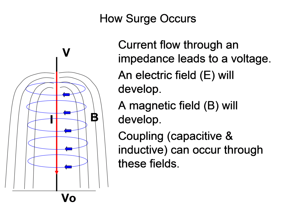
There are also inductive effects possible to internal wiring and equipment with even a well designed lightning protection system. The current of a massive direct lightning strike to a structure creates a magnetic field extending from the conductors, so any alternate circuit proximate may experience some added voltage through induction. Although the lightning protection Standards and the National Electrical Code only discuss surge protection on internal equipment as optional, this may be a critical protection need for the owner. Protection of audio/video components, communications systems, computer equipment and/or process machinery may be of great importance to the quality of the establishment, continuity of business without interruption, and the physical protection of equipment users. SPDs installed at utilization equipment should provide protection for all circuits feeding the device to provide a common ground point. Since systems of utilization equipment are generally specific for the facility, an individualized assessment will normally be needed to determine cost effective solutions.

When surge protection devices send energy to the ground system this instantaneous connection of all wiring systems functions to provide potential equalization for those metallic systems, just as bonding between the lightning protection system components and alternate building system grounds provides common interconnection. Advances in technology continue to change the environment of structures where we live, work, and enjoy entertainment. The application of SPDs along with the current carrying components and interconnection of grounded building systems provides the complete package for a full lightning protection system to protect structure, people, and equipment within.
Inspection & Maintenance
The exposed components for a lightning protection system are copper, aluminum, or other metal designed to carry current, provide bonding connections, and remain functional in an open weather environment. As with any other building element made of similar materials, oxidation or corrosion of components would not be expected under normal conditions for an extended period, or the normal “lifetime” of the structure. System components concealed within construction between the roof and grade are protected against weathering and abuse. The grounding electrode system may be protected from atmospheric conditions of weathering, but is subject to potential degradation from soil compositions and moisture. A proper initial installation might be expected to provide protection forever or at least for the reasonable useful life of a particular building.
There are additional realities of construction, our use of buildings, and even unknowns in local conditions that require consideration of maintenance for the lightning protection system. A passive grounding system like lightning protection is not easily assessed by laymen – you can’t flip a switch or turn on a faucet to see if it is in working condition.
There are obvious times when changes to the structure create a need for maintenance or extension of the original system. Re-roofing the building, making additions to the building’s structural frame, or adding vent stacks or antennas for new internal processes are obvious areas needing review and treatment. Not so obvious, but reported as the greatest cause for required review of systems is the habit of workers from other trades removing and failing to reinstall system components because they do not understand the importance of the total lightning protection system design. It is also possible that a neighboring process stack will emit a substance carried by the wind toward your system components that works to degrade materials at a much faster than expected rate. Any and all of these items call for periodic inspection and maintenance to assure the system is functional when placed under lightning strike conditions, but it certainly could be ignored with serious unintended consequences.
A program of inspection and possible maintenance should be implemented to assure continued effectiveness of the system on the structure. A visual inspection can be accomplished yearly using a checklist and modest training from your lightning protection provider to account for any minor repairs like loose fittings, improper anchoring, damage to exposed cables, replacement of removed hardware, or damage to surge protection devices. This could be done by a regular building maintenance technician or even the building owner with some guidance. If a lightning protection professional is not used for every yearly inspection, then at five year intervals it would be important to have a “testing” inspection by bringing in a knowledgeable individual – inspector or installer – for a more thorough examination.

A complete testing inspection would include the visual checks along with continuity testing to verify system effectiveness from roof to grade, and ground testing to validate the concealed underground electrodes function. A quality assurance program designed for maintenance of your lightning protection system will eliminate surprises that could lead to disastrous consequences.
The implementation of a lightning protection system includes some art, science, craftsmanship, and technological intuition. This is a specialized industry with its own Standards designed purpose specific to deal with nature’s great random destroyer. As in any endeavor the background, training, and certification of the individuals involved in the design, installation, and inspection of a complete lightning protection system determines the ultimate quality. The Lightning Protection Institute focuses our efforts to educate professionals, owners, users, and the general public on safe and effective lightning protection and provides quality resources through our membership to accomplish this important service for the entire construction industry.